


Read the entire Reef Sanctuary thread. Jumping on the ATS bus.
So it's been a little slow at work, and since I have AutoCAD and my dad makes acrylic items for antique dealers (display cabinets, holders, etc) I decided to design an ATS for a customer (or 2) of mine. These JPEGs are a little bug but I didn't want to lose resolution. Before I had my Dad start working on this bad boy, I figured I'd post it here and see if I missed anything.
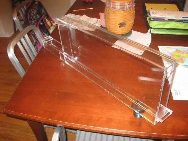
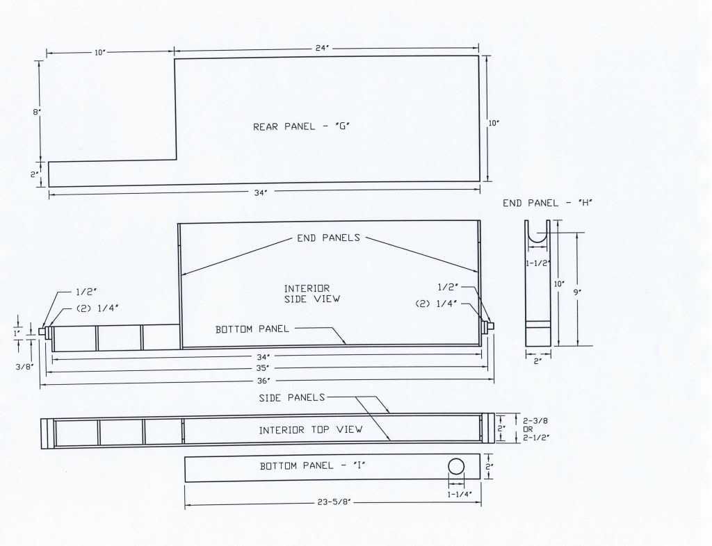
Here's the back panel and the interior framing
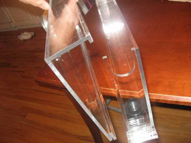
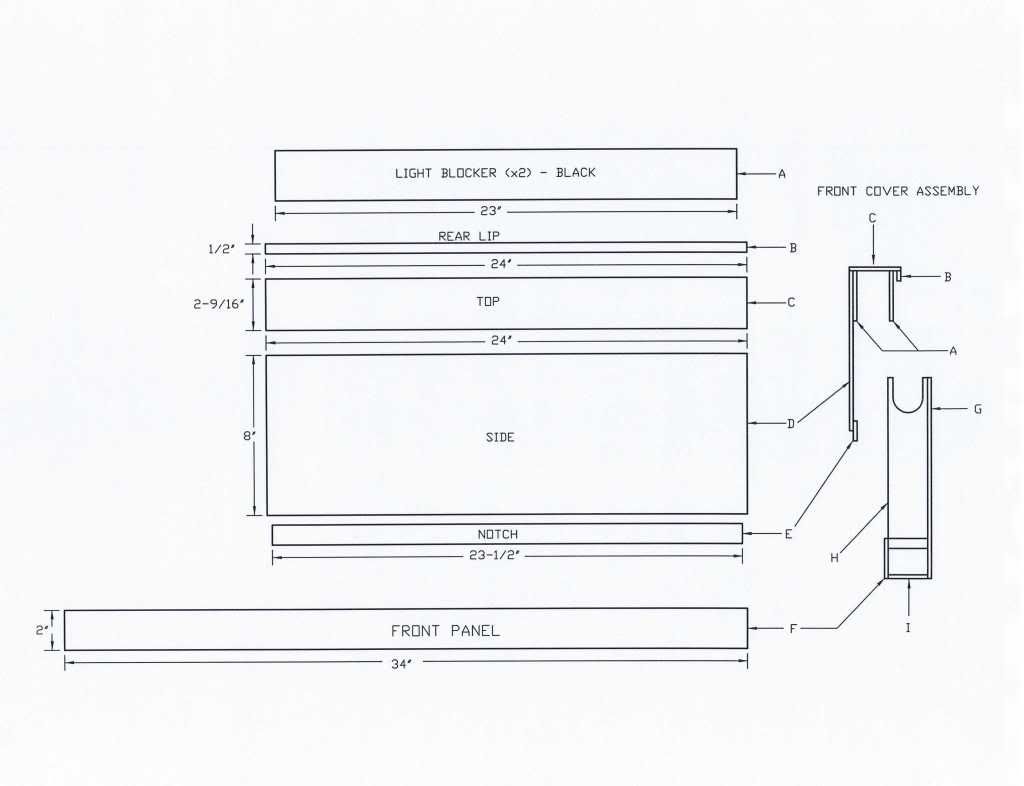
The front access panel and assembly
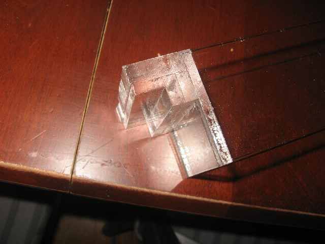
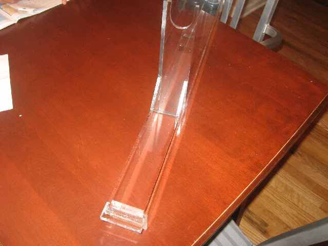
And the front and side assembly
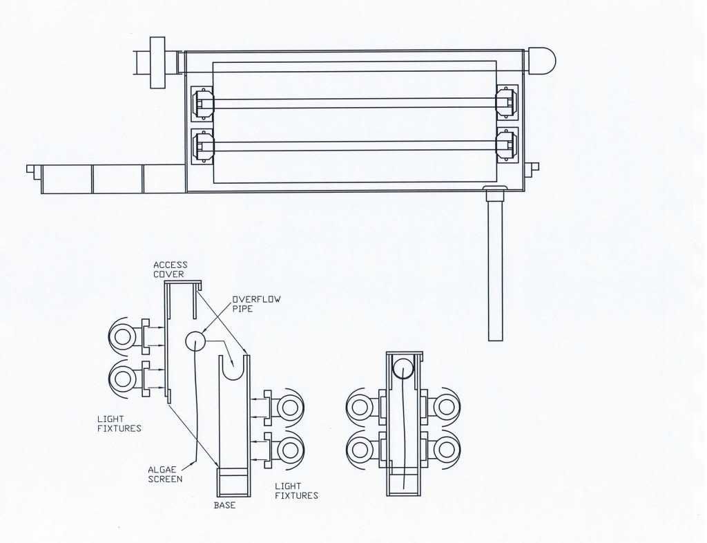
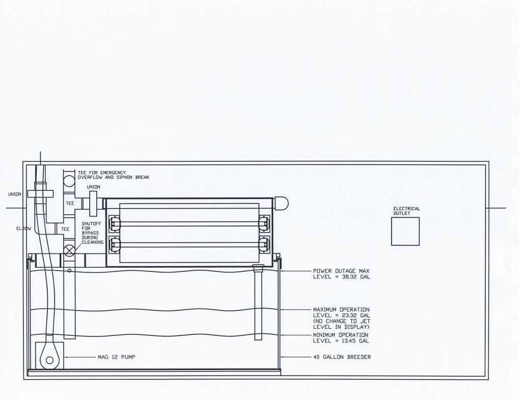
Here's the sump cabinet, 40G breeder, overflow plumbing, and ATS assembly.
Front View
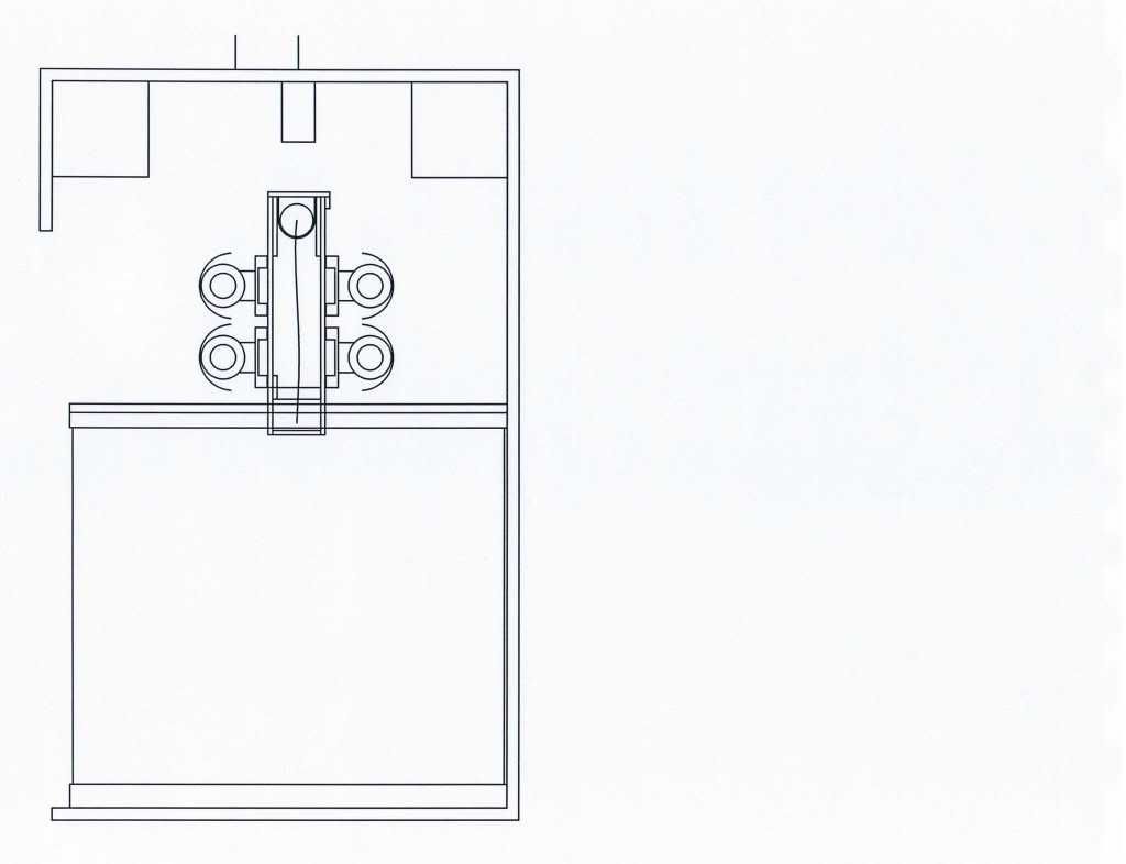
End View
The usable screen area is 20" x 6+" for 120 sq in. There are 4 F24T5HO lamps, 2 on each side, and I found the deal of the month on this one, from Avant Garde'n, which specializes in hydroponics. 4 pack of 3000K red/bloom lamps for $20, 8 pack for $32. Kick-a!! http://www.aghydroponics.com/T5-Fluores ... -s/379.htm. Incidentally, I discussed what I am designing with him and he was totally stoked about the idea, and mentioned a nearby university that was doing some kind of study on aquatic plants that had the ability to absorb heavy metals. This idea might get some heavyweight backing sometime soon!
I am using a Fulham Workhorse 5 Ballast. I am using Ice Cap end caps and standoffs, and Sunlight Supply TEK II T5 Reflectors. I marked the distance from center of bulb on one side to center of bulb on the other side as just over 6", but they're HO and the TEK II reflectors are top notch, so I figure this should be OK.
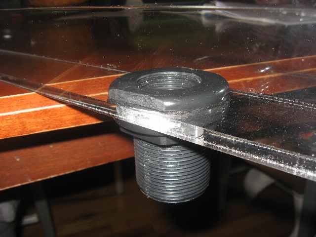
The overflow is designed with ease of maintenance in mind. From the bottom of the tank, there is a union to disconnect the entire assembly. Then it goes into a 90, and then into a series of 3 stacked tees. Under the first one is a shutoff valve that can be opened to allow the water to flow while cleaning the screen (ignore the placement, it's just representative at this point). The next tee up feeds the screen tube. The next tee will have an emergency clog overflow pipe running back into the sump, and the top end of the tee will remain open for a siphon break, so if for some reason the flow is enough to start going through the emergency flow, it wouldn't stop minimal flow from the screen. As I'm writing this, I'm thinking that might not be necessary since the screen itself would provide a siphon break. Hmmmm...
Anyways, from the tee to the screen tube is another union to disconnect the screen. The front panel of the unit locks in place and is removeable- the lights mount to it, so you would just open the bypass shutoff and remove the front panel and set it aside, unscrew the union, and lift the screen out. At this point, you could swish it in the sump if you wanted the pods in your DT. Then you do your duty with the screen and replace, reconnect, cover, open the disconnect, and you're off and running again.
So...any problems that anyone sees?
EDIT: One of things that I have to verify are the current flow rate into the sump. Right now, the pump is on the far right side and has a 3 foot horizontal return component that will be eliminated with the new design, plus a little less head pressure from a higher sump level, so my flow reading I will get will probably be low, but will at least tell me if I my screen is correctly sized. Also, I have to verify all the dimensions of the PVC parts, I estimated based on prior builds for filter sock systems and some quick measurements.
 Reply With Quote